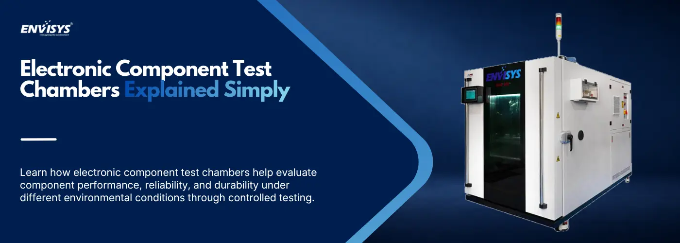
A circuit board that works perfectly on a bench in an air–conditioned lab tells you almost nothing. That board will end up in a car bonnet at 110°C, on a telecom tower through a monsoon, or in a phone left on a dashboard in June.
Electronics fail in ways that are easy to miss until they matter. A solder joint cracks after enough thermal cycles. Moisture creeps under a conformal coating and corrodes a track. A capacitor drifts until a circuit stops meeting its timing.
Test chambers make those failures happen early, where an engineer is watching. This guide explains what the chambers are, what they test, and how to choose one without over–specifying.
What Are Electronic Component Test Chambers?
An electronic component test chamber is an insulated enclosure with heating, refrigeration, airflow management and a programmable controller, built to hold and change conditions precisely while a component sits inside. Most control temperature and many add humidity. The specimen is usually powered and monitored during the test, since an idle board behaves nothing like one dissipating heat under load.
What separates an environmental simulation chamber for electronics from a general purpose one is scale and precision rather than principle. Electronics work involves small specimens, tight tolerances and many test points, so chambers tend to be smaller, more accurate and better equipped with feedthroughs. For wider context, this explanation of environmental test chamber principles and types covers the fundamentals.
Why Electronic Components Need Environmental Testing
Heat is the primary enemy. Semiconductor life falls sharply as junction temperature rises, electrolytic capacitors dry out faster, and every dissipated has to go somewhere.
Cold causes different problems: displays respond slowly, batteries lose capacity, oscillators drift, and plastics and solder turn brittle.
Humidity is the quiet one. Moisture penetrates packaging, corrodes tracks and bond wires, creates leakage between conductors and, in surface–mount parts, causes popcorning when absorbed water flashes to steam during reflow.
Thermal cycling is where most field failures originate. Silicon, copper, FR4 and solder all expand at different rates, so every temperature change works the joints between them until a microcrack becomes an open circuit. Electronic component environmental testing turns years of that into weeks, which is the only way to know a design’s reliability before production.
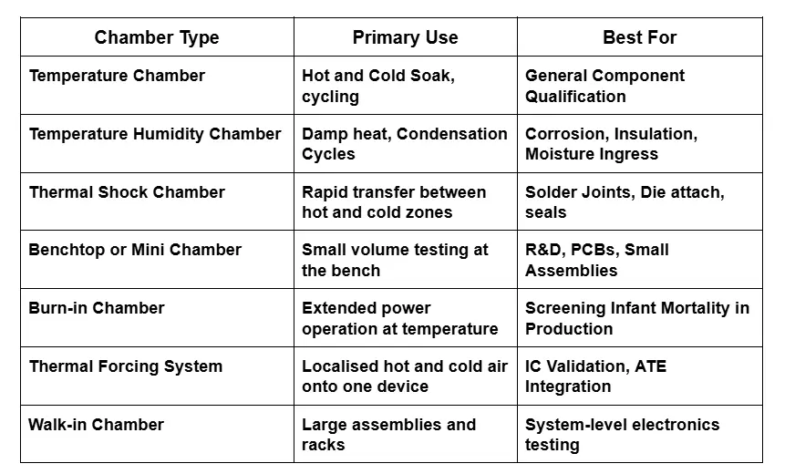
Types of Electronic Component Test Chambers
Key Tests Performed Using Electronic Component Test Chambers
1.Temperature Cycling Test
The component ramps between hot and cold extremes with dwells at each end, commonly minus 40°C to plus 125°C, repeated for hundreds or thousands of cycles. This is the workhorse of electronic component validation testing, accumulating fatigue in solder joints and interconnects at a controlled rate, with electrical parameters measured at intervals to track when performance starts shifting.
2. Thermal Shock Testing
Instead of ramping, the specimen transfers between separately conditioned zones in seconds, so its surface changes temperature far faster than its core. That gradient concentrates stress where materials meet, which is why shock is unusually good at exposing weak die attachments, marginal solder and voids in encapsulation that gradual cycling never finds.
3. Humidity Resistance Testing
The specimen is held at high humidity, most commonly 85°C and 85% RH, sometimes with bias applied so leakage currents are measured under realistic conditions. The test finds corrosion, dendrite growth, package delamination and falling insulation resistance. Highly accelerated stress testing pushes further, using pressure to speed moisture penetration.
4. Burn–In Testing
Components run powered at elevated temperature, often 125°C, for many hours. Defective parts fail early, so burn–in forces infant mortality failures to happen in the factory rather than in the customer’s product. This matters most in automotive, medical and aerospace supply, where a field failure is expensive.
5. Accelerated Life Testing
Stress levels are raised beyond normal operating conditions so degradation happens faster, then models such as the Arrhenius relationship estimate real–world life from the results. This is how manufacturers make lifetime claims without waiting a decade. It works only if the acceleration does not introduce failure modes that would never occur in service, so choosing stress levels carefully matters more than choosing extreme ones.
Industries That Use Electronic Component Test Chambers
Semiconductor and electronics manufacturing leads, covering ICs, packaging, PCB assemblies and passive components. Automotive follows closely, since a modern vehicle carries dozens of control units and sensors facing under–bonnet heat, and EV programmes add power electronics and battery management systems.
Aerospace and defence require qualification against demanding standards, telecommunications tests outdoor equipment and base stations, and medical device manufacturers need reliability evidence for regulatory approval. Consumer electronics, industrial automation and renewable energy manufacturers test inverters, controllers and sensors the same way.
How to Choose the Right Electronic Component Test Chamber
1.Define Your Test Requirements First
Work from the standard your customer cites, not from a catalogue. Pull out the temperature range, humidity range, ramp rate, dwell times and cycle count, then check a chamber meets all of them rather than most. Ramp rate is the one people miss: a chamber that reaches your temperatures slowly fails the procedure even though its range looks right.
2. Match Chamber Type to Test Application
The table above matters here. Thermal shock needs two conditioned zones, not one chamber ramping quickly. Burn–in needs sustained powered operation and enough electrical feedthroughs. Device–level IC work is often better served by a thermal forcing system than by conditioning a whole chamber for one chip. Buying the wrong type is more expensive than buying the wrong size.
3. Evaluate Control Accuracy and Uniformity
Control accuracy at the sensor and uniformity across the working volume are different numbers, and uniformity decides whether every specimen sees the same test. Ask for uniformity measured under load with mapping data. Around 1.5°C is typical for smaller volumes, and a tightly packed chamber will not achieve its rated figure, so leave clearance for airflow.
4.Consider Future Scalability
Chambers last fifteen years and test requirements grow, so size for the assemblies you expect in two or three years rather than today’s boards. Check the controller supports more channels than you currently need, and confirm feedthroughs can be added, since retrofitting ports later is awkward and often not possible.
Key Features to Look for in an Electronic Component Test Chamber
Programmable multi–step profiles, so a sequence combining ramps, dwells and humidity runs identically every time.
Adequate sealed cable feedthroughs for powering and monitoring the specimen, since most electronics work needs the part live during the test.
Data logging with timestamps, specimen thermocouple channels and an export format you can still open in five years. Reports showing achieved profile against target are what auditors ask for.
Stable humidity control with a stated accuracy rather than just a range. Over–temperature protection independent of the main controller. And remote monitoring, which earns its cost on long unattended runs where an overnight fault otherwise wastes the cycle.
Relevant Testing Standards for Electronic Component Chambers
IEC 60068 is the base international series, with Test Na for thermal shock, Test Nb for temperature change and Test Cab for damp heat, and most commercial electronics programmes reference it.
JEDEC standards govern semiconductors, including JESD22–A104 for temperature cycling, JESD22–A106 for thermal shock and JESD22–A101 for steady–state temperature humidity bias. IPC–9701 is widely used for solder joint reliability. Automotive work references AEC–Q100 for integrated circuits and AEC–Q200 for passives alongside ISO 16750, while MIL–STD–883 applies to microcircuits in defence programmes.
Confirm which document governs your programme and write it into the purchase order, since standards specify ramp rates and dwell times, not just temperatures.
Why Manufacturers Partner With Envisys for Electronic Testing Chambers
Envisys builds environmental chambers for electronics across the range this article covers rather than a single product line.
That includes benchtop chambers in 30, 64, 80 and 100 litre volumes covering minus 60°C to plus 150°C with accuracy around ±1.0°C and humidity from 35% to 95% RH, suited to R&D benches and PCB work. Larger ET–series chambers extend to minus 70°C and plus 180°C with humidity from 10% to 98% RH, and ETS thermal shock chambers cover minus 45°C to plus 210°C with transfer under ten seconds.
For device–level work, Envisys builds thermal forcing systems as a temperature control device for electronic chips, delivering conditioned air onto a chip through a compact head from minus 40°C to plus 125°C, with ATE integration for production lines rather than conditioning a whole chamber for one device.
Chambers are engineered around the specimen rather than configured from a fixed platform, and installation, commissioning and calibration are handled directly.
Final Thoughts
Choosing a chamber for electronics comes down to three things: the standard you must satisfy, the specimen you are actually testing, and whether the chamber holds conditions while nobody is watching.
Match the chamber type to the test before comparing prices, since a fast–ramping single chamber is not a thermal shock chamber and never will be. Then check uniformity under load, not just accuracy at the sensor. Get those right and electronic product environmental testing becomes a routine part of development rather than a bottleneck before every release.
FAQs
- What is an electronic component test chamber used for?
It reproduces environmental conditions so components can be tested before they reach service. Typical uses include qualifying new designs across their temperature range, finding manufacturing defects through cycling and shock, checking moisture resistance, screening production units through burn–in, and generating reliability data customers require.
- What tests can be performed in an electronic component test chamber?
Temperature cycling, high and low temperature soak, thermal shock, damp heat and humidity bias testing, burn–in, and accelerated life testing. Combined testing with vibration or altitude is possible with the right configuration. The chamber type determines which tests it can run, so match the equipment to the method.
- Which industries use electronic component test chambers?
Semiconductor and electronics manufacturing, automotive including EV programmes, aerospace and defence, telecommunications, medical devices, consumer electronics, industrial automation and renewable energy. Anywhere electronics face temperature or humidity variation in service, or where a customer specification demands the data.
- What standards apply to electronic component environmental testing?
IEC 60068 provides the base international methods. JEDEC standards including JESD22–A104, A106 and A101 govern semiconductors. IPC- 9701 covers solder joint reliability, AEC–Q100 and AEC–Q200 apply to automotive components, and MIL–STD–883 covers defence microcircuits. OEM specifications are often stricter.
- Can electronic component test chambers be customized?
Yes, and most electronics programmes need some. Common changes include internal dimensions, additional cable feedthroughs, viewing windows positioned for cameras, specialised fixtures, and interfaces to external test equipment. Ask whether a supplier engineers to your drawing or only configures options within a fixed platform, since that decides what is actually possible.

